SAAB J35F/J Draken
Hasegawa (07241)
1:48
Started: May 2008
Finished: Sep 2008
Link to Gallery

The Saab 35 Draken ('The Kite' or 'The Dragon') is a Swedish fighter-interceptor developed and manufactured by Svenska Aeroplan Aktiebolaget (SAAB) between 1955 and 1974. Development of the Saab 35 Draken started in 1948 as the Swedish air force future replacement for the then also in development Saab 29 Tunnan dayfighter and Saab 32B Lansen night fighter. It featured an innovative but unproven double delta wing, which led to the creation of a sub-scale test aircraft, the Saab 210, which was produced and flown to test this previously-unexplored aerodynamic feature.

The Saab 35 Draken is known for, among other things, its many "firsts" within aviation. It was the first Western European-built combat aircraft with true supersonic capability to enter service and the first fully supersonic aircraft to be deployed in Western Europe. Designwise it was one of, if not the first, combat aircraft designed with double delta wings, being drawn up by early 1950. The unconventional wing design also had the side effect of making it the first known aircraft to be capable of and perform the Cobra maneuver. It was also one of the first Western-European-built aircraft to exceed Mach 2 in level flight, reaching it on 14 January 1960

The Draken functioned as an effective supersonic fighter aircraft of the Cold War period. Even though the type was designed and intended as an interceptor, it was considered to be a very capable dogfighter for the era. In Swedish service, it underwent several upgrades, the ultimate of these being the J 35J model. By the 1980s, the SAF's Drakens had largely been replaced by the more advanced Saab 37 Viggen fighter, while the introduction of the more capable Saab JAS 39 Gripen fighter was expected in service within a decade, although delayed
KIT OVERVIEW - Hasegawa 1:48 SAAB J35F/J Draken (07241)
I built my Draken mostly from the box as no aftermarket was available at the time. As the Drakens came to the end of their service life, the airframes started to look dirty and tired and I attempted to capture this in the painting and weathering of the model.

BUILD - Hasegawa 1:48 SAAB J35F/J Draken (07241)
A quick dry fit of the cockpit reveals a good level of detail. The left side looks a bit sparce, but more on that in a little while. The seat looks very plain (like most kit seats) and will need the most attention to bring it upto scratch.

The cockpit from another angle. I am sure resin sets will be produced for this kit, however I don't want to wait for them. I think that with some good references we can make some small enhancements and get a good result

Here we see the tub from the other side. According to my references, something will need to be done about the lack of detail of the left side near the throttle quadrant

In accordance with my references (primary one was the Aerofax Minigraph #12), I've used some plasticard and reheat PE cockpit details to "busy up" the left side of the tub

To enable easier access to the back of the intake trunking for painting, I decided to cut off the rear blanking plate (the intake on the right has had the surgery applied). A new plate will be made from card when all the interior painting is complete

The cockpit sills benefited from a little added detail from 10thou card

Test fitting the enhanced tub into the fusleage. Here also we can see the work done to the head of the seat. Also notice how the seat cushion has been sanded down to look less "square" and give it more of a cloth look

The cockpit from the opposite side. The canopy pressure seal (on the rear bulkhead the top of the seat) was created from stretched sprue. The seat will receive a complete harness and belts from lead foil later on

Leaving the cockpit behind for now, i decided after studying many photos that the flaperons had to be dropped. Here we can see the two parts to the flaps. The inner portion currently attached to the fuselage half and the outer attached to the wing section

The inner sections are cut away using a PE razor saw and a fresh #11 blade. The masking tape is there in case of a slips with the saw or knife (to minimise damage)

For those of you who are nervous about hacking up you new $50 kit, here is a step by step guide to separating flaps/ailerons from the wing. This wing is a good example of a difficult one as the two counter balance weights need to be cut out and kept with the flaps

Step 1: Using a knife, slowly score along the kit panel line which represents the join. Here you can see I have cut clean thru the two counter balance weights to make the separating cut easier

Step 2: We now need to remove the sections of the counter balances from the main wing. In this step we see how I used a PE razor saw to make the vertical cuts

Step 3: To complete the removal of the counter balance section, I use the tip of a knife to score along the horizontal panel line. Do this carefully to avoid overcuts onto the wing surface. If you do slip, just fill the overcut with super glue to repair

Step 4: Last step is to glue the counter balances back onto the flaps. When dry these will be sanded and filled to restore the detail. The wing upper and lower halves have been joined here and a general cleanup performed

With the flaps removed, I have dry fitted the fuselage tale cone and decided (after consulting reference pics) that more detailing is required here (as it will now be visible with the flaps dropped)

This wing root section on the real aircraft is hollow with a sheet metal cover. The cover wil be added later, for now I am opening up the rear part of the wing root to allow a hollow appearance

The tub recieves a coat of primer. The scratchbuilt sections now blending (hopefully seamlessly) into the model

The primary cockit colur has been added and panel detail picked out in black. The colour I used was Humbrol 30

A closer shot of the tub

The insturmental panel as provided by Hasegawa is well detailed and quite accurate

With the cockpit interior painted, the sills need to receive a coat of silver. Here everything has been masked in preparation for that

The tub following a wash of burnt umber and dry brushing with silver

The completed tub, which intentionally look worn and tired, as most of the Drakens looked late in the service life

With the tub all tucked snugly inside and the fuselage top and bottom joined, its time to see how much nose weight is needed. Well I think we could get away with none, however I am a cautious fellow, so you can bet the nosecone will be loaded

Here we see the exhaust. Its a bit hard to see, but notice how thick the outer lip is ?

Here I have taken less than 30 seconds to thin the outer lip down to a much more scale realistic size. Little touches like this make all the difference when viewed on the final model and take such little effort to achieve

Speaking of small touches that look great, intake vents are a favourite of model manufacturers for leaving solid (see the right hand intake). Using a fine drill and blade tip, you can quickly hollow these guys out and they look so much better for it

It was at this point that this kit started to remind me of the AV-8B I built sometime back. Hasegawa have engineered the kit to allow them to do multiple variants, which means many more "optional" panels and sections that need to attached by the modeller (rather then by the molding process). Anyway, this in itself is not a bad thing. Its only a pain when each of these optional panels does not fit well. So it is with the two panels on the wing leading edges (some variants of the Draken have gun ports on both sides etc). In this pic, you can see the end result of poorly fitting panel being filled with superglue and sanded back to shape. This will later be rescribed to bring the panel lines back

The join between fuselage and tailcone was also pretty bad. It dipped noticeably in the middle and much super glue was used to fill the depression. This photo shows the end result. The primed section either side of the panel line shows the extent of the work done to correct this problem

The same join as seen from the bottom. Not as bad as on top, but still more work than you'd like to correct it

The nosecone has now been added, and panel lines sanded and primed to ensure a suitable result

So, now we finish work on the wing root. If you were a little confused earlier when I was explaining why I was hollowing this section out, hopefully its all clear now. Here I have punched a series of holes in a 10thou card and it has been glued to the wingroot

Once the glue had dried, a sharp knife is used to trim the excess away and the illusion of depth behind the wing root is achieved. Again, a small touch, but one that will add to overall affect of realism

Hasegawa give us the option of using a clear navigation light or solid one. I prefer the effect of a clear light. Here you see on the left wing, I have cut away the plastic section, glued in the clear part, sanded it flush to the wing (the fit was not brilliant) and then buffed it back to clear. The righthand one will be done next)

The drop tanks are pretty good, but the fins are way over scale (as can be seen here). I will cut these off and replace with plasticard

Another part that was not a good fit was the intakes. I had to do some serious sanding to get them to blend into the fuselage section. Using super glue as a filler allowed me to rescribe the panel lines that had been lost due to the sanding. The pic shows the end result

The port side also had the same fit problems and required substantial sanding work

The Draken intake lips are natural metal. Here the intakes have had their Stainless Steel Alcad applied. The very front edge of the intake lip is a darker Burnt Iron color, which is about to be applied, hence the masking

The intake lip has now been painted (Humbrol Gun Metal) and the masking removed. I really like the buffable Gun Metal paint from Humbrol as it gives a very realistic finish, and can be brushed on if needed

The join between the fuselage spine and the tail section needed a bit of attention. Here a light coat of Tamiya Basic Putty has been applied to the joint line and will be lightly sanded shortly

The kit supplied RAM Air Turbine propeller has blades that are obviously way over scale. I noticed that the recently released Eduard PE set (ED48597) contains a PE set of blades that should look nice

Rather than go down the Eduard path, I decided to see what could be done with the kit part. Using a sharp blade, I carefully trimmed the thickness of each of the blades down to a more realistic size. I'm happy with the result

The Air Turbine assembly has been completed with some simple added piping detail added from 10thou brass wire. This turbine unit is always seen deployed on powered down Drakens.

Where possible, I like to display the model with a nose wheel that has a slight turn in it (looks a bit more dynamic I think). Here we see the nose wheel assembly after I cut it into sections. The brass wire pin is used to provide strength to the part when it is glued back together, it also ensures that everything lines up properly

The overscale fins on the drop tanks have been replaced with 10thou plastic card

The flaps have now been re-attached to the wing. This is a little tricky as once the flaps are dropped they don't want to line up properly. Some trimming and harsh words

The main undercarriage doors have the landing lights attached. Hasegawa provides these lights as clear parts (great idea). I've added a small section of copper wire to give a little more detail

Here we see an overall shot of progress. Most of the upper/lower antennas have been attached. The next major step will be to start the painting of the undersurface

The FLIR pod which will be attached to the lower forward fuselage has a clear section on its nose. This clear part has been painted using Tamiya clear (Green + Smoke) and is now being masked. This type of masking can be tricky as you are masking a part that has a compound curve. You can see from the photo that I have not tried to make the tape conform to the curve of the nose, rather wrapping it around

Once the tape (which gives the sharp demarcation) is in place, the top of the tape is filled with Humbrol Maskol. This helps to hold the tape in place and also masks the top section

Several of the smaller parts, have received their coat of Alclad Stainless Steel

The wheels (all 5 of them) have been masked. Also can be seen are the drop tanks which are bare metal

The center section of the Draken fuselage is bare metal. The wheel wells and wing leading edges are also bare metal. All these areas have been painted in Alclad Stainless Steel

One of the more visible features of the Draken cockpit is a pair of support bars in the windscreen. Hasegawa does not provide these, so I fashioned them from brass rod (15thou). Here you can see the front ends have been fastened to the windshield and the rear (top) ends have yet to be cut to length. Extreme care needs to be exercised here as we are drilling (and shortly be gluing) into clear parts. There are no second chances with clear parts like canopies

Preparing the bottom of the aircraft for its coat of paint, the rear fuselage has beem masked to protect the Alclad metal finish

Needing a break from the masking, my attention returned back to the unfinished seat. Using my references (and the Eduard PE sets instruction page

Here we see the windshield with the now finished support bars. These where painted prior to final installation and gluing

A simple but effective tip for painting parts that are close to clear parts (like these suppport bars) is to use a small piece of paper as a mask. Here I have simply slipped the paper behind the support bars and then touched up any blemishes caused in the process of fitting and gluing them. You can see I don't need to be careful about painting as the paper protects the clear windshield. Much easier than trying to fit masking tape behind there

The canopy is next with some minor detailing from plasticard and the beginnings of interior masking

Here we can see the canopy masking is complete and a pair of PE mirrors have been added. The mirrors (from Reheat) are provided in a chrome silver finish, and here I have used Maskol to mask the inside face

The undersurfaces have now received their colour coat (Humbrol H128)

With the undersurfaces dry, its time to finish up the cockpit so it can be masked up. The HUD has been fashioned from clear acetate film (discard the kit part, its way too thick). The shroud has also received a light dry brush to bring out the detail

The windshield has been glued in place (using thin Super Glue) and masked. The cockpit tub has also been masked. I'm a bit worried about the paint chipping evident on the engine intake. This may cause me some grief when I mask up for the upper coats. Time will tell

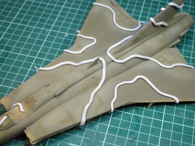
With the lower grey dry, its time to mask up for painting the uppersurfaces. Here I am masking the curved demarcation line on the nose section (just below the cockpit). Snakes of Blu-Tack have been used, with backfill of Tamiya tape

The lower masking is complete. Extra tape has been used in the forward fuselage area as I will need to bring the airbrush lower on the sides as the camo wraps over the leading edge and partially underneath

When looking for reference material for my build, I came across several photos of drakens. This photo (credits to Mark Van Der Vielt on Airliners.net) was one I liked as it showed a weary Draken with faded paint, visible repairs and generally looking run down. The colours used when painting my model would be based on this photo, rather than the Hasegawa instructions

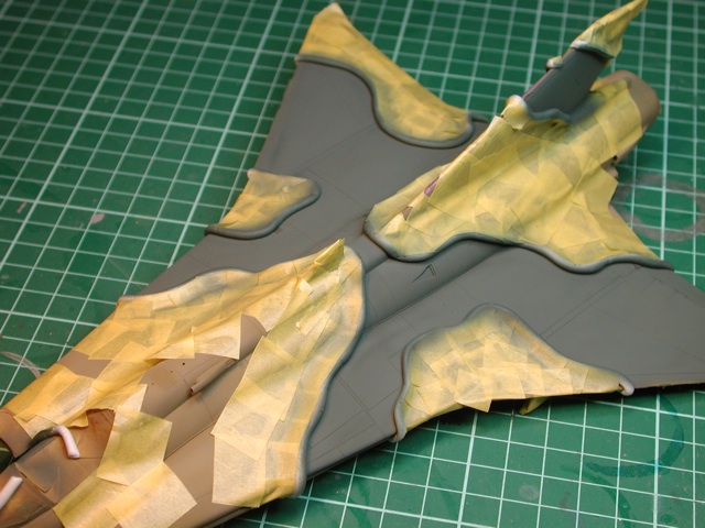
First coat was Humbrol H155 (Olive Drab). Once this was dry, it was time to mask the demarcations for the second camo color. You may notice that I have done some preliminary fading of the paint using a lightened (heavily thinned) mixture
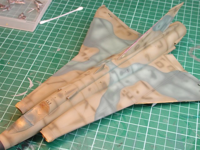
The second camo colour has been applied. This is a custom blend of roughly these proportions. H30 (Dark Green) Two Parts + H25 (Blue) One Part. On reflection, I probably would have added more blue (and possibly darker), say H15 (Midnight Blue)
As with the first colour, I have done some initial fading of the paint

With the masking removed, I went back to my references and decided to increase the intensity of the weathering. Right now it looks overdone, but I believe that when I apply the decals and panel line wash and oil wash, the fading should look about right (fingers crossed
The masking has also been removed from the the lower surfaces. The alclad metal paints really do look fantastic

After a coat of Future, its time for the decals. Because I have taken so long to finish this kit, a couple of third party decal options are now available. However, none of them are any better than the kit options, so I used the Hasegawa decals. In this picture you can see the results of applying MicroSol (softening agent) to the decal. This is perfectly normal and after 30mins the decal settles back down and snuggles into the panel lines etc

Decaling is complete. There are actually very few decals on the Draken. I chose an aircraft that did not have the large numbers in white on the wings. I wanted the weathering to be the main feature people notice, not the big numbers

After a coat of Future, its time for the decals. Because I have taken so long to finish this kit, a couple of third party decal options are now available. However, none of them are any better than the kit options, so I used the Hasegawa decals. In this picture you can see the results of applying MicroSol (softening agent) to the decal. This is perfectly normal and after 30mins the decal settles back down and snuggles into the panel lines etc

The main ladder has been removed from the sprue and is ready for careful bending and gluing

A problem that had me stumped for a while (2 days) was that when I followed the Eduard instructions, the ladder just did not look or fit correctly. Once I compared the instructions to photos of the real ladder I could see what Eduard had done wrong. Its a simple matter (once you realise) of gluing part 7 lower down on part 1 as per my red arrows

The ladder assembly is now complete. This was easily one of the most frustrating PE sets I have worked with. It is very delicate and everytime I adjusted one part, another would break or come unglued

Final assembly is now taking place. Here we see the completed cockpit, with a spare parts helmet to add some character

The final appearance of the top camo scheme, complete with fading, panel lines and oil washes


